Rebuilding Procedures
Flite Technology's 38 Step General Procedure For Feed Screw Rebuilding
Primary Flights Only
1. Prepare screw for pre-work inspection. Remove plastic, rust, etc., utilizing chemical cleaners, heat of grit blasters, as required.
2. Complete detailed pre-work inspection report. Record screw LD. Numbers, flight O.D.s, flight O.D.s, flight widths widths, root O.D.s, O.A.L. seal dimensions, drive conditions, Rockwell hardness, itemizes additional damage, and a wear analysis is implemented.
3. Screws are checked for metal fatigue, cracks by dye penetrant or megna flux testing. (Note: As through as feed screws are inspected, some cracks do not show up until they are being welded or ground. Hence, screws are checked a number of times during the rebuilding process.)
4. Processors is called to confirm price, delivery and scope of repair before any work is done. 5. Customers requesting blueprints of their screws for future placement of manufacture orders are made at this time.
6. Detailed four page, step-by-step work orders are issued to the shop. Work orders have questions for each machine operator to state the method, material, and dimension or specifications obtained at his work station. 7. Screws are centered and straightened, removable tips are taken off, and tip counterbores are checked for concentricity.
8. Hard chrome or other plantings/coatings, if present on the root diameter, are chemically removed.
9. Stress relieving is done as required.
10. Existing hardfacing is entirely ground off. Some of our competitors try welding new hardfacing onto old hardfacing to save money and then wonder why it is full of cracks and falling off.
11. If screws are extremely undersized or have to be severely underground to remove existing hardfacing, a "buffer" layer of steel may be applied between the new hardfacing and the base metal of the screws.
12. Screws are pre-heated and maintained to exact temperatures required for specific hardfacing material and welding methods.
13. Major weld repairs of modifications are completed. Serious flight width deterioration is rectified. Please note: Flite Technology, Inc., considers minors root repairs, bearing section and register rebuilding as part of the rebuilding process and does not charge for this additional work or service.
14. Flight surfaces are cleaned with chemical solvents and/or abrasive which is required for excellent adherence.
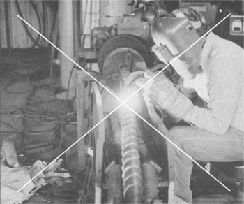
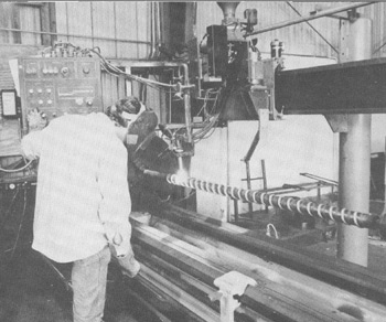
15. Hardfacing is applied. Welded samples, is required, are available for metallurgical and microstructure evaluation.
16. Screws are immediately placed in and covered with a vermiculite for nad approximate 48 hours cool down period to eliminate cracking as much as possible.
17. Stress relieving is done, as required.
18. Straightened occurs.
19. Rough grind screws to an even over-size dimension.
20. Stress relieving done, as required
21. Screw flight sides are ground
22. Damage requiring weld repair is milled at this time.
23. Rough polishing begins.
24. Stress relieving done as required.
25. Through in-process visual inspection, aided as necessary, by dye penetrants or magna flux testing, is preformed.
26. Extruder screws are checked for cooling hole blockages and are hydrostatically tested. All damaged threads are corrected
27. Injection screws have registers ground concentric with root diameter and screw ends are faced off. Extruder screws with removable rips have connecting ends ground for good tight fir.
28. Finish polishing.
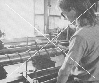
29. Extensive dimensional and surface inspection is done.
30. Plating or root treatments are applied, as required.
31. Antiseize compound is applied to tip threads.
32. A final check for straightness is preformed
33. Finish grinds the O.D and seal area.
34. Buff finishes the root diameter.
35. Stamp identification number into part.
36. Complex final inspection is preformed.
37. Rust inhibitor is sprayed onto screw.
38. Screws are wrapped in oiled paper. The unit is crated and shipped.
How Can One Company Charge $1500 For Rebuilding a Feed Screw and Another Company Charge $850?
Hardfacing Item #1
Brand X 
Some companies are
using tig and mig welding to speed up the hardfacing time, but the
result is low Rockwell Hardness, and the screws wear out prematurely. |
Flite Tech 
Flite Technology has invested a considerable amount of money in the latest welding equipment and techniques, providing our customers with a hardfacing with good adherence qualities, fewer voids and cracks which results in a considerably longer screw life. |
Straightening Item #2
Brand X 
Many companies only straighten their screws with
a hammer; YES, we said a hammer. Can you imagine how much stress
the base steel and the hardfacing experience in the process,
and you wonder why your screw has cracks. |
Flite Tech 
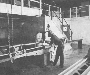
Flite Technolgy has a hydraulic press especially designed for straightening feed screws and long shafts. Feed screws are treated gently and are brought back to straightness with no damage to the screw’s structural integrity, coating, or hardfacing. |
